

Choosing the Right Camera for a Machine Vision Application
Choosing the right camera for a machine vision application never starts with a brand, a catalogue, or an arbitrary number of megapixels. In a well-designed machine vision system, the camera selection is driven by the application. That sounds logical, but in practice we still often see engineers focusing too early on resolution, interface, or price, while the fundamental questions have not yet been clearly defined. What exactly does the system need to see? Which detail is critical? What is the size of the field of view? Is the product moving? And does the system only need to detect something, or also measure, read, or classify?
It is precisely this initial analysis that makes the difference between a system that looks good on paper and one that performs reliably in production. The selection of an industrial camera should therefore be built up step by step. Based on experience in machine vision, the following sequence works best: first selecting the sensor, then calculating the required pixel resolution, followed by determining the field of view, deriving the minimum sensor size from that, then defining the required frame rate, and finally choosing the most suitable interface.
This sequence prevents a common design mistake: selecting a camera that later turns out to be unsuitable in terms of optics, bandwidth, or light sensitivity. Resolution should be derived from the application, not from the temptation to choose as many megapixels as possible “just to be safe.” In many cases, over-specification actually leads to smaller pixels, higher demands on the lens, and less robust image formation.
1. Always Start with the Application
A camera is not a standalone component, but part of a complete machine vision system. That is why the selection process always starts with the application requirements. The key questions are: what is the total inspection area, what is the smallest relevant detail, whether colour information is truly required, how fast the process runs, and whether the object is stationary or moving during image acquisition. In practice, it is primarily the smallest relevant detail that determines the rest of the design. This could be a scratch, an edge, a code, a dimensional difference, an OCR character, or the presence or absence of a component. If this feature is not clearly defined, the rest of the camera selection will inevitably become uncertain.
2. The First Fundamental Choice: The SensorCamera selection starts with the sensor. This involves considering factors such as resolution, pixel size, sensor format, shutter type, and the choice between monochrome and colour. That last point, in particular, is decisive in many industrial applications.
| 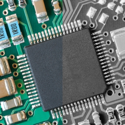 |
3. The Impact of a Colour Camera on Effective Resolution: The Bayer Pattern
Most industrial colour cameras are single-chip cameras with a Bayer filter pattern. This means that not every pixel captures full RGB information. Each pixel measures only one colour component: red, green, or blue. The two missing components are later reconstructed through interpolation. At its core, this is a smart and widely used technique, but it does have consequences for image quality. The first consequence is that the effective detail resolution is lower than that of a monochrome camera with the same number of pixels. A monochrome sensor uses every pixel directly for spatial detail information, whereas a Bayer sensor does not, since part of the color information has to be reconstructed in software.
The second consequence is reduced light sensitivity, as colour filters block part of the incoming light. As a result, colour imaging is often more demanding in terms of lighting and signal-to-noise ratio. In practice, this means that a color camera often requires more nominal pixels to achieve the same level of detail as a monochrome camera. For precise measurements, small features, low contrast, and high-speed applications, monochrome is therefore usually the safer choice.
4. Rolling shutter or global shutter?
In addition to the choice between monochrome and color, the shutter type is also important. In machine vision, the choice is typically between rolling shutter and global shutter.
With a rolling shutter, the image lines are not exposed at exactly the same moment, but are read out line by line. This works well when objects are stationary or moving slowly, and when there is little to no motion during image acquisition. Rolling shutter sensors are often cost-effective and widely available. With a global shutter, all pixels are exposed simultaneously. This is especially important for moving objects, high-speed conveyor systems, pick-and-place applications, robot guidance, and measurements where shape or positional distortion is unacceptable. A global shutter prevents straight lines from appearing skewed and avoids object deformation caused by sequential sensor readout.
In practice, the choice can be summarized simply: for static or slowly moving applications, a rolling shutter can work well, but for dynamic industrial applications, a global shutter is usually the safest and most robust option.
5. Do color cameras always transmit three times more data?
No, not necessarily. This is an important nuance that is often presented too simplistically in many texts.
It is true that a full RGB image contains significantly more data than a monochrome image. If a camera outputs, for example, 24-bit RGB instead of 8-bit monochrome, the data stream is approximately three times larger.
In that case:
• Mono8 = 8 bits per pixel
• RGB8 = 24 bits per pixel
In this situation, the data rate of RGB is indeed about three times higher.
However, a single-chip color camera with a Bayer pattern does not necessarily have to output its data as a full RGB image. Many cameras transmit raw color data as Bayer8, Bayer10, or Bayer12. In that case, only one color sample per pixel is transmitted, and the raw data rate is often comparable to that of a monochrome camera with the same bit depth.
The technically correct conclusion is therefore: a color camera does not automatically transmit three times more data than a monochrome camera. It depends on the selected pixel format and whether the camera outputs raw Bayer data or full RGB data.
6. Determine the Required Pixel Resolution
Once it is clear which sensor type is required, the necessary resolution can be calculated. In machine vision, a simple but powerful rule applies: the smallest relevant feature and the desired field of view together determine how many pixels are needed. The calculations below are examples to illustrate the method. In practice, the exact required resolution also depends on contrast, lighting, lens quality, product variation, tolerances, and the level of robustness required in the application.
|
This is a calculation example to illustrate the approach. In a real application, the final design choice may be higher, for example due to contrast loss, product variation, or reliability requirements.
7. OCR is calculated differently from standard feature inspection
For OCR, the approach is different. Typically, you do not base the calculation on line thickness or the smallest defect size, but on the minimum character height and the number of pixels required by the OCR software to reliably recognize a character. This can vary depending on the software platform, library, font, contrast, and print quality. In practice, a guideline such as 25 × 15 pixels per character is often used, but this is not a universal rule. It is a practical starting point that should always be validated later using real images and the selected OCR tool.
Example: OCR application on a label of 20 × 80 mm
Assume:
• the label has dimensions of 20 × 80 mm;
• the smallest text to be read has a character height of 5 mm;
• the OCR software used requires approximately 25 pixels in character height for reliable recognition.
First, you determine the required scale: 25 pixels / 5 mm = 5 pixels per mm
If the field of view in width corresponds to the label width of 80 mm, the minimum required horizontal resolution becomes: 80 × 5 = 400 pixels
For the height of 20 mm, this results in: 20 × 5 = 100 pixels
Theoretically, this leads to approximately 400 × 100 pixels for the label area. This is also a calculation example to illustrate the methodology. In practice, we rarely design exactly at this lower limit. You need margin for label position, rotation, print variation, contrast loss, and tolerances in product presentation. For robust OCR, additional resolution headroom is therefore usually included deliberately.
8. Determine the Field of View
The field of view, or FOV, is the visible area of the object that is projected onto the sensor. The FOV is determined by the product dimensions, but also by positional tolerances, mechanical variation, and any need to observe multiple features simultaneously. A common mistake is selecting the FOV too tightly. In theory, this may seem efficient, but in a production environment it quickly leads to issues with small shifts, rotations, or tolerance variations. A robust vision setup therefore always accounts for practical margin.
9. From Field of View to Minimum Sensor Size
Once the field of view and required resolution are known, you can determine which sensor format is suitable. The relationship between sensor size, magnification, and field of view is essential.
In practice, this means: magnification = sensor size / FOV
The sensor size therefore partly determines the required lens magnification. A larger sensor is often advantageous, as it typically allows for larger pixels at a given resolution. Larger pixels generally result in better light sensitivity, improved signal-to-noise performance, and less demanding requirements for the lens. At the same time, the lens must be capable of properly and sharply illuminating the entire sensor area. Here too, experience plays an important role: many designers underestimate how much influence the lens has on the final system resolution. Small pixels require a lens with high optical performance across the entire field of view.
10. Determine the Required Frame Rate
Only after the resolution, FOV, and sensor concept are defined do you determine the frame rate. The required frame rate depends on how fast the object changes or moves. A frame is a complete image, and the number of frames per second must match the dynamics of the process. In a triggered system, you can often calculate it simply: fps ≥ number of products per second × number of images per product. For continuously moving products, the exposure time also plays a crucial role. A camera may have sufficient fps, but still produce unusable images if the exposure time is too long and the product moves too far during acquisition. A practical guideline is that an object should move less than approximately one pixel during the exposure to avoid motion blur.
11. From Resolution and Frame Rate to Data Throughput
Once resolution, a bit depth, and frame rate are known, the required data throughput can be calculated: Data per second = width × height × bits per pixel × fps. This is the key factor for selecting the interface. Take, for example, a camera with 2448 × 2048 pixels at 30 fps. At 8-bit monochrome, this results in approximately 1.20 Gbit/s, or about 150 MB/s. With Bayer8, the raw data throughput is comparable. With full 24-bit RGB, this increases to approximately 3.61 Gbit/s, or about 451 MB/s. You should always include margin, as the raw data rate is not the same as the net usable image data. Packet overhead, headers, and protocol information reduce the effective throughput. Therefore, interface selection should always be done conservatively.
12. Only Then Choose the Right Interface
In practice, USB3 Vision, GigE Vision, and CoaXPress are three of the most commonly used camera interfaces in machine vision. The most suitable interface depends on bandwidth, cable length, robustness, system architecture, and the industrial environment.
USB3 Vision
USB3 Vision is a widely used choice for compact systems and setups where the camera is located close to the host PC. It is accessible, fast, and cost-effective. For laboratory systems, test setups, and simple standalone vision solutions, USB3 Vision is often a logical choice. In industrial environments it can work well, but in terms of cable length and mechanical robustness it is generally less forgiving.
GigE Vision
GigE Vision is one of the most popular standards in machine vision. It uses existing Ethernet infrastructure, making it widely applicable. Based on practical experience, GigE Vision is often better suited for industrial environments than USB3 Vision, especially when longer cable lengths, integration into machinery, and robust installation are important. For many industrial applications, GigE Vision is therefore often preferred, as it offers a good balance between performance, cost, flexibility, and reliability.
CoaXPress
CoaXPress is designed for high data rates over coaxial cables and is therefore particularly well suited for demanding industrial applications with high resolution, high frame rates, or line scan cameras. CoaXPress is also often better suited for industrial environments than USB3 Vision, mainly due to its robust cabling and reliable high data throughput. On the other hand, CoaXPress typically requires a frame grabber card in the host PC. This means that, in addition to the camera and cabling, extra hardware is required. In practice, this results in higher costs and often a more complex system architecture. CoaXPress is therefore mainly interesting when the required performance exceeds the capabilities of GigE Vision or USB3 Vision.
A practical additional note is that for GigE Vision and USB3 Vision, it is advisable not to use hubs when maximum performance is required, as they can limit or disrupt effective data transfer.
13. Choosing Between a Smart Camera and a PC-Based Machine Vision System
In addition to selecting the sensor, resolution, and interface, it is also important to determine whether the application is best implemented using a smart camera or a PC-based machine vision system. A smart camera combines the camera, processor, and vision software in a single compact housing. This makes it an attractive solution for relatively simple applications where a compact installation and limited integration effort are desired. In practice, smart cameras are mainly used for straightforward inspections where a single camera view is sufficient and where limited processing power is required. Typical examples include simple presence checks, position detection, basic code reading, simple OCR, label inspection, or basic OK/NOK inspection. In such applications, a smart camera can be an efficient and cost-effective solution. When the application becomes more complex, requires multiple camera viewpoints, demands high resolution or high frame rates, or involves more advanced image processing and extensive data integration, a PC-based machine vision system is usually the better choice. A PC-based system offers more processing power, greater flexibility, more expansion options, and typically more freedom in software selection, data storage, and communication with other systems.
The practical decision is therefore quite clear: for simple, single-view inspections, a smart camera can be an excellent choice, but for more complex or demanding applications, a PC-based machine vision system is usually the more future-proof solution.
14. Praktische beslisvolgorde
In practice, this is the best sequence for selecting a camera:
- Define the application.
- Determine the smallest relevant detail.
- Choose monochrome or colour.
- Choose rolling shutter or global shutter based on motion dynamics.
- When using colour, account for lower effective resolution due to Bayer interpolation.
- Calculate the required pixel resolution.
- Determine the FOV including margin.
- Based on that, select a suitable sensor or chip size.
- Verify that the lens can support the sensor size and pixel pitch.
- Determine the required fps and maximum exposure time.
- Calculate the data throughput.
- Only then choose the interface.
- Finally, determine whether a smart camera is sufficient or if a PC-based machine vision system is required.
Conclusion
Choosing the right camera for a machine vision project always starts with the application and never with a catalogue. First, you determine which detail must be visible or detectable. Then you decide whether monochrome or color is functionally required. Next, you determine which shutter type fits the motion dynamics of the application. After that, you calculate the required resolution, define the field of view, select an appropriate sensor size, and verify whether the lens can truly support this combination. You then determine the required frame rate, calculate the data throughput, and based on that, select the appropriate interface. For many industrial applications, a monochrome camera remains the best choice, as every pixel directly contributes to detail representation and light sensitivity. A colour camera is valuable when colour is truly relevant, but it always requires additional attention to effective resolution, lighting, and data processing. With Bayer colour cameras, it is also important to understand that the effective detail resolution is lower than with monochrome, and that the data throughput is not automatically three times higher unless full RGB is transmitted.
The choice between rolling shutter and global shutter is also critical for a robust machine vision system. For stationary or slowly moving objects, rolling shutter can work well, but for fast or dynamic industrial processes, global shutter is usually the safer choice.
When selecting the interface, USB3 Vision, GigE Vision, and CoaXPress are among the most commonly used standards. In practice, GigE Vision is often preferred for many industrial applications. It offers a strong balance between performance, cost, integration flexibility, and robustness in industrial environments. Especially when longer cable lengths, reliable communication, and easy integration into machinery or production lines are important, GigE Vision is often the most logical choice.
CoaXPress is technically a very powerful solution for high resolutions and high speeds, but it typically requires a frame grabber card. This means that, in addition to the camera and cabling, extra hardware costs and often a more complex system architecture are involved. As a result, CoaXPress is mainly interesting when the required performance truly exceeds the capabilities of GigE Vision or USB3 Vision.
The choice between a smart camera and a PC-based machine vision system is also part of the design. Smart cameras are mainly suited for simple, straightforward inspections with a single camera view and limited processing requirements, while PC-based systems offer more flexibility and processing power for more complex applications.
The core of a good camera selection is therefore not choosing as many pixels as possible or the fastest interface, but making a well-founded technical decision based on the application. That is exactly where knowledge, experience, and practical insight in machine vision systems make the difference.
Struggling to find the right camera for your machine vision application?
You can browse our complete range of machine vision cameras on the all cameras page. If you need help selecting the right camera for your application, feel free to contact our vision specialists for technical advice.