Continuous inspection is used in production processes where the product does not yet have a fixed beginning or end during inspection. Examples include plastic wire, extrusion profiles, film, metal strip, textile, carpet or other continuous material that is cut, sawn, stamped or rolled later in the process. At that stage, you are not inspecting a single discrete product, but a continuous material moving through the machine at a constant speed.
This is why continuous inspection is technically different from a standard inspection of individual parts. With a separate product, a camera can capture a complete image as soon as the part is in position. With continuous material, the product keeps moving. The inspection must therefore be linked to the material movement, so defects are not only detected, but their exact position in the process is also known.
In continuous inspection, the length of the product is not known at the moment of image acquisition. The vision system must therefore not only detect a defect, but also link the position of that defect to the material displacement. That link determines whether the defect can later be cut out, marked or used for process control.
Why continuous inspection often takes place before cutting or sawing
Continuous material is often inspected before it is divided into separate products. In an extrusion process, this may be a plastic profile that is sawn later. In metal processing, it may be strip material that is used further down the line in a stamping process. In carpet production, the material is often cut or rolled only after production.
If defects are already visible before the material is separated into individual products, the machine can take them into account. A defective section can, for example, be cut out of the material, or the cutting position can be selected so that the defect falls outside the usable final product. In other cases, inspection is necessary because a deviation may cause machine problems later in the process. A dimensional error, thickening, damage or hole can later lead to faults, downtime or loss of quality.
In practice, this means that continuous inspection is not only a form of quality control, but also a form of process protection. The vision system must be fast enough for the line speed, accurate enough for the defect type and stable enough to operate continuously without image build up, trigger timing or illumination becoming a new source of errors.
Why a line scan camera is often the logical choice
Continuous inspection is often performed at high speeds, sometimes several metres per second. At the same time, the required accuracy can be high. This is exactly where a line scan camera is strong. A line scan camera does not capture a complete 2D image at once, but records one image line at a time. As the material moves, these lines are built up one after another into one long image.
The line scan camera is usually triggered by an encoder. Each encoder pulse determines when a new image line is captured. This keeps the image scale in the direction of movement linked to the actual material displacement. This is important because speed variations would otherwise immediately cause distortion in the image.
The major advantage of a line scan camera is that the length of the composed image is flexible. The software can determine how many lines are combined into one inspection image. As a result, a defect can be longer than one standard camera image without automatically falling outside the inspection frame. For continuous material, this is an important advantage compared with a fixed area scan image.
Another advantage lies in the illumination. Because the camera only sees one line at a time, only one narrow line needs to be illuminated properly. A powerful line light can illuminate the inspection area in a very targeted way. This makes high light intensity more achievable, which is important because line scan cameras often work with very short exposure times.
The practical disadvantages of a line scan camera
A line scan camera is technically strong, but not always simple. Installation requires more attention than with an area scan camera. The camera, encoder, line light, objective and software must be accurately matched to each other. An error in trigger frequency, encoder resolution or mechanical alignment can immediately lead to distortion, irregular image lines or missed defects.
Focusing is also more difficult than many engineers expect. Without movement, a line scan camera keeps looking at the same narrow line. You therefore do not automatically get a recognisable 2D image in which sharpness is easy to assess. Adjusting the objective and illumination therefore requires more experience, especially with small pixels, high resolution or reflective materials.
Industrial robustness is important when selecting the encoder. We usually recommend an encoder with 24 V pulses instead of 5 V signals. In an industrial environment, 5 V signals are more sensitive to interference, cable effects and EMC problems. Because every encoder pulse directly affects image build up, an unreliable trigger signal can lead to measurement errors or irregular image lines.
Sensor length, pixel size and light requirements
When selecting a line scan camera, it can be tempting to immediately choose more pixels. However, that is not always the best choice. Keep the sensor length as small as technically possible. A 2K line sensor with 2048 pixels can be better in many applications than a 4K sensor, as long as the required resolution remains achievable. Fewer pixels often mean simpler data processing, lower light requirements and more robust integration.
Pixel size plays an important role here. The smaller the pixel, the less light is collected per pixel. With line scan cameras, this is especially critical because each line must be illuminated separately and the exposure time is often very short due to the speed of the material. This is why a pixel size of at least 3.45 µm is often a practical lower limit. Larger pixels are favourable in many industrial situations because they collect more light and make the illumination less extreme.
This is also why the camera, objective and illumination must be selected together. Higher resolution has little value if the illumination is insufficient or if the objective cannot transfer the required resolution. For a reliable setup, machine vision cameras, objectives and machine vision illumination must be selected as one complete imaging chain.
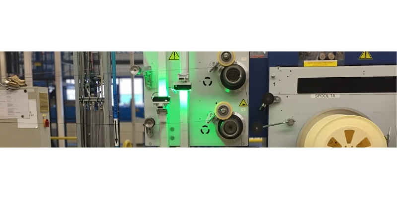
Illumination in continuous inspection: bright field and dark field
In line scan inspection, the camera is usually positioned perpendicular above the material. The line light is often placed at an angle. By changing the illumination angle, the same material can appear very different. This difference is decisive for the reliability of defect detection.
With bright field illumination, the surface is illuminated relatively directly. This often makes colour differences, spots, contamination, stains or surface variations more visible. With dark field illumination, the light hits the surface at a low angle. This often gives more contrast to scratches, dents, holes, edges and structural deviations.
The right illumination angle therefore depends on the defect type. A scratch that is clearly visible in dark field may almost disappear in bright field. Conversely, a discolouration may be clearly visible in bright field, while dark field mainly enhances structure and edges. Illumination must therefore not only be selected based on brightness, but based on the contrast formation of the specific defect.
When an area scan camera can still be suitable
Although a line scan camera has many advantages in continuous inspection, area scan cameras are also used in practice. This can be a good choice when the required defects fit within one image and the required resolution is achievable. An area scan camera captures a complete 2D image in one exposure. As a result, mounting, focusing and initial testing are often easier than with a line scan camera.
An area scan camera also has an advantage in exposure time. Because you do not trigger per line, but per image, you can often work with a longer exposure. This means less light is required than with a line scan camera. The disadvantage is that the entire image area must be illuminated homogeneously. This is usually more difficult than illuminating one narrow line, especially with wide materials or reflective surfaces.
When defects are longer than one area scan image, multiple images can be stitched together. This can work well, but there are limitations. Lens distortion at the edges and corners can cause a defect at the side of the image to be represented differently than in the centre. Software correction can partly solve this, but not always completely. This effect is much less relevant with a line scan camera because the same image line is used continuously.
Using an area scan camera as a line scan camera
With some area scan cameras, it is possible to use only part of the sensor or a narrow region of interest. With many IDS area scan cameras, for example, a method can be set up where the camera is easier to mount and adjust than a classic line scan camera, while continuous images can still be built up.
The advantage is that the area scan camera is more recognisable during installation. You can focus more easily, check the field of view and adjust the illumination. At the same time, with the right software, you can still build continuous image information so that defects longer than one standard image remain visible.
This approach is not a replacement for a true line scan camera in every application. At high speeds, very high accuracy or large material widths, a line scan camera often remains the better choice. But for many AI or vision applications in a production environment, an area scan camera can be a practical intermediate solution, especially when ease of installation, cost and flexibility are important.
Line scan camera or area scan camera: the choice depends on the system
The choice between a line scan camera and an area scan camera should not be based on camera type alone. The application determines the right solution. Important parameters include material width, line speed, smallest defect, defect length, required resolution, available space, encoder integration, illumination type, software architecture and budget.
A line scan camera is usually stronger when the material is truly moving continuously, the speed is high, defects have variable length and the inspection must be accurately linked to material displacement. An area scan camera is often more practical when the defect fits within one image, the speed is lower, the installation must remain simpler or when the application is first built as a proof of concept.
The difference in price and integration effort is also relevant. A line scan camera setup is usually more expensive and requires more work during installation and software integration. In return, it is often technically more reliable for true continuous inspection. An area scan camera is easier to start with, but may later create limitations in speed, distortion, stitching or defect length.
Conclusion
Continuous inspection requires a different way of thinking than the inspection of individual products. Because the material has no fixed beginning or end, the vision system must follow the product continuously. At high speed and high accuracy, a line scan camera is often the best technical choice, especially when the camera is triggered line by line by an encoder and the image is built up in software.
However, an area scan camera can be a good choice when defects fit within one image or when ease of installation is more important than maximum continuity. In some cases, an area scan camera can even be used in a line scan like way, creating a practical middle ground.
The right choice only becomes clear when camera, objective, illumination, encoder, interface and software are assessed together. For continuous inspection, the camera is never a standalone component. The reliability of the system depends on the complete imaging chain. If you are unsure whether a line scan camera or an area scan camera is the best choice for your application, it is wise to first define the product speed, material width, defect size and illumination conditions before selecting the camera.