
Carrier tape inspection is often one of the final visual checks in the semiconductor industry before components are shipped to the customer. At this stage, the devices have usually already been inspected several times. For example after molding, marking, trimming, forming or electrical testing.
Still, an additional inspection is often performed once the components are placed in the carrier tape. That makes sense, because things can still go wrong during placement into the tape. A device can be rotated incorrectly, the wrong variant can end up in the tape, the marking may be difficult to read or a pin may be bent during handling.
Carrier tape inspection is therefore usually not a high precision process measurement, but a final check for orientation, correct product type, readability and visible handling damage.
What is inspected?
A common inspection task is checking the orientation of the device. In practice, this is often done by checking pin 1. The software looks for a recognizable orientation feature, such as a dot, cutout, marking or text position. If this feature is in the wrong position, the device has been placed incorrectly in the carrier tape.
It is also common to check whether the correct component type is being shipped. This is usually done with OCR on the text printed on the package. For components that look very similar, this is an important final check.
Pins or leads can also be inspected at this position. The exact pin position, length or coplanarity is often already measured earlier in the process with a more accurate system. In carrier tape inspection, it is usually a practical check: has a pin become visibly bent or damaged during placement into the tape?
That difference is important. You should not try to turn a simple final inspection into a precision measurement system, unless the mechanics, tape guidance, camera, lens and lighting have also been designed for that purpose.
Camera choice
Camera selection starts with the smallest detail that must be detected reliably.
When text needs to be read or verified, you first look at the requirements of the OCR software. How many pixels high does a character need to be? How many pixels are needed across the character width? Based on that, you determine the required resolution on the object.
If pins, edges or small defects also need to be evaluated, the smallest critical detail determines the practical resolution. You should not only look at the theoretical pixel size. In practice, the device is not always in exactly the same position inside the pocket. There is play in the carrier tape, slight movement may occur and the trigger position also has a tolerance.
For detecting clearly bent pins, this is usually not a major problem. These defects are often clearly visible. For accurate length measurement or position measurement of pins, it becomes a different matter. In that case, the complete mechanical and optical setup must be built much more precisely.
Field of view
The field of view is usually selected based on the dimensions of the pocket in the carrier tape. Do not make the field of view exactly the same size as the pocket. Allow a few millimeters of margin. The complete pocket must always be visible, even when the tape shifts slightly or the trigger position varies.
With moving tape, the transport direction is especially important. The trigger accuracy determines how much extra margin you need in that direction. A smaller field of view gives more detail, but less process margin. A larger field of view gives more margin, but costs resolution.
The right choice is therefore always a compromise between detail and robustness.
Lens choice
A high resolution camera only makes sense if the lens can support that resolution. The lens must provide sufficient optical resolution for the selected sensor and pixel size.
Do not only look at the center of the image. In carrier tape inspection, text, pins and package edges can also be located toward the outer part of the field of view. This is exactly where lower quality lenses often show a drop in contrast and sharpness.
In the lens datasheet, this is usually shown in the MTF graph or specified as optical resolution in lp/mm. Check especially whether the lens remains good enough in the area where the critical inspection details are located.
A setup can look fine in the center of the image and still become unreliable when the important details are near the edge of the image.
Lighting
Lighting often has more influence than the camera. Especially with black or dark grey packages, shiny pins and reflective pocket walls.
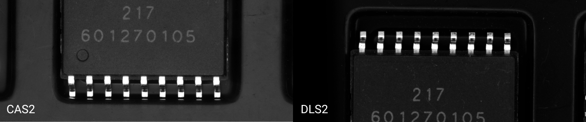
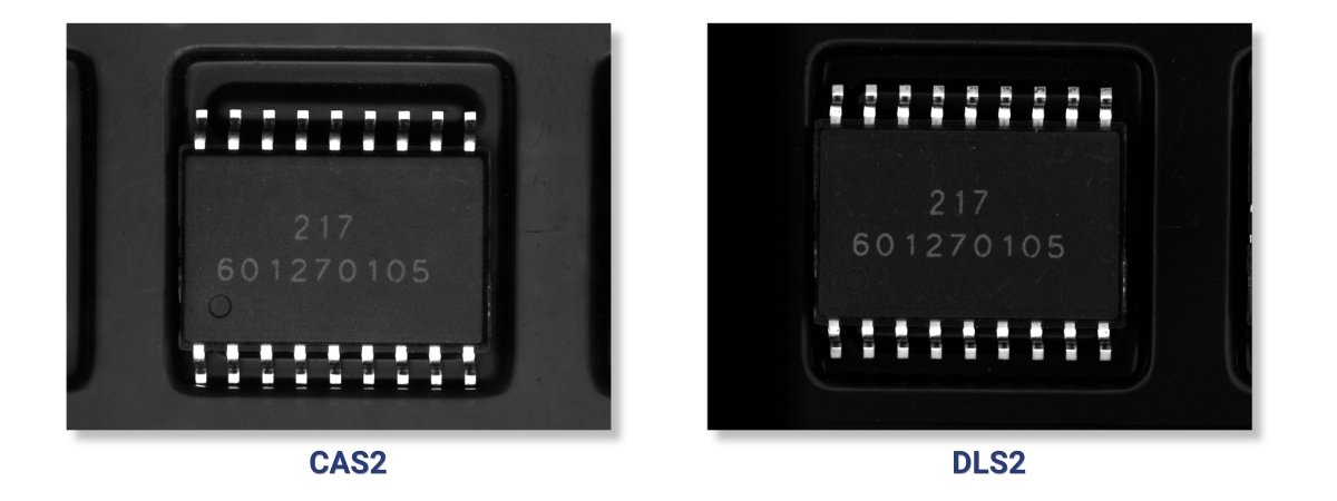
Coaxial lighting, such as CAS lighting, often works well for text, marking and pin 1 inspection. The lighting is easy to mount and provides enough contrast on many packages to detect text or an orientation mark. For OCR and pin 1 inspection, this is often a good first choice.
The disadvantage is that shiny parts can also create reflections. With some carrier tapes, you may see reflections of pins or pin tips in the wall of the pocket. For text inspection only, this is usually not a problem. For pin length or pin shape inspection, it can be disturbing.
A diffuse square light, such as a DLS2 light, can solve this more effectively. The light hits the device at an angle, which makes reflections calmer and reduces the influence of surface structure. As a result, text can often become more stable to inspect and package damage may become more visible.
On the other hand, a pin 1 mark can sometimes become less visible. A mark that gives clear contrast with coaxial lighting can almost disappear with diffuse angled lighting.
One or two images
Which lighting works best depends on the inspection task.
If OCR and pin 1 inspection are leading, coaxial lighting is often the logical choice. If reflections, package damage or visible pin damage are more important, diffuse lighting may be better.
In some cases, one lighting setup will not solve the complete inspection properly. Then it is better to capture two images. One image with coaxial lighting for text and pin 1. One image with diffuse lighting for the surface, pins and reflection sensitive details.
This makes the inspection slightly more complex, but it prevents you from forcing one lighting type to do inspection tasks it is not really suitable for.
Practical approach
Do not start with the camera. Start with the inspection question.
Does the system only need to check whether the device is present and positioned correctly? Does the text need to be read? Does pin 1 need to be checked? Do pins only need to be checked for visible damage, or do they actually need to be measured? Does package damage also need to be inspected?
Only after that do you select the camera, lens, lighting, trigger and mechanical setup. This way of working fits how you build a machine vision system in practice: first translate the application into image quality, resolution, lighting and timing, and only then select the right components.
Preferably use real samples. Not only good products, but also rejected products. Incorrectly rotated devices, poor marking, damaged packages and bent pins. Only then can you see whether the selected lighting and resolution provide enough margin.
Carrier tape inspection often looks simple, but small differences in tape, package material, marking, reflection and position can have a major effect on image quality.
What it comes down to in practice
Carrier tape inspection is a practical final check. You verify whether the correct device is placed in the pocket, whether the orientation is correct, whether the text is readable and whether no visible damage has occurred during handling or placement into the tape.
Reliability is not only determined by camera resolution. The combination of camera, lens, lighting, field of view, trigger accuracy and mechanical guidance determines whether the system runs stable in production.
For text, OCR and pin 1 inspection, coaxial lighting is often a strong solution. For reflections, surface inspection and visible pin damage, diffuse lighting may be better. When both inspection tasks are important, capturing two images is often the most robust solution.
When selecting components for a carrier tape inspection setup, the camera, lens, lighting, trigger and mechanical guidance should be chosen together. In many cases, a practical test with real good and rejected samples is the fastest way to determine which setup gives enough production margin. Machine Vision Shop can help you select the right machine vision components for this type of inspection, whether you want to build the system yourself or first validate the image quality with sample testing.