
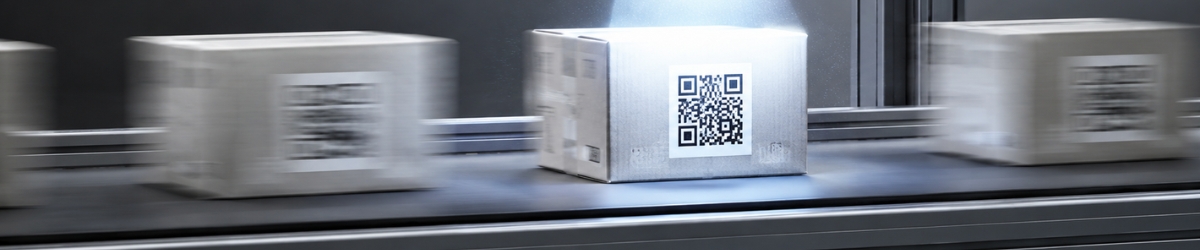
A QR code that can be read reliably on a stationary product may become much more difficult to read once the product is moving on a conveyor. During image acquisition, the product travels a certain distance while the sensor is exposed, causing fine details and edges to spread across multiple pixels. This results in motion blur, commonly referred to in machine vision as pixel blur or pixel smear.
Reducing the exposure time limits pixel smear, but it also reduces the amount of light reaching the sensor. The correct exposure setting therefore depends on several factors, including pixel resolution, conveyor speed, illumination, light pulse duration and duty cycle. In this article, we calculate these parameters using a QR code inspection on a moving conveyor as a practical example.
QR code inspection parameters
QR Code Version 3: 29 × 29 modules;
module size: 0.9 × 0.9 mm;
conveyor speed: 7 m/min;
minimum of four pixels per module;
maximum permitted pixel smear: 0.8 pixel;
product pitch: 100 mm;
camera with a global shutter.
Without the quiet zone, the QR code measures:
29 × 0.9 = 26.1 mm
With a quiet zone of four modules on each side, the required area becomes:
(29 + 8) × 0.9 = 33.3 mm
A rolling-shutter camera is not suitable for this application because the image rows are exposed sequentially rather than simultaneously. As the product continues to move while the individual rows are being captured, the geometry of the QR code can become distorted. With a global shutter, all pixels are exposed at the same time, preventing this type of motion-induced geometric distortion.
Calculating the pixel resolution
The decoding algorithm used in this example requires at least four pixels across each QR module. With a module size of 0.9 mm, this determines the required object-space resolution:
R = 0.9 mm ÷ 4 pixels = 0.225 mm/pixel
Each pixel may therefore represent no more than 0.225 mm on the product. For motion-blur calculations, always use the pixel resolution in the direction of movement, as this is the direction in which the image will smear. Together with the required field of view and the available working distance, this value can then be used to select a suitable camera and lens combination.
Calculating the maximum exposure time
The amount of pixel smear can be calculated using:
Pixel smear = (product speed × exposure time) ÷ object resolution
A conveyor speed of 7 m/min corresponds to:
7,000 mm ÷ 60 = 116.7 mm/s
The maximum exposure time can therefore be calculated as:
Maximum exposure time = (permitted pixel smear × object resolution) ÷ product speed
With a maximum permitted smear of 0.8 pixel, this gives:
(0.8 × 0.225) ÷ 116.7 = 0.001543 s = 1.543 ms
A practical exposure setting is therefore 1.5 ms. At this exposure time, the actual pixel smear is:
(116.7 × 0.0015) ÷ 0.225 = 0.78 pixel
Using a significantly shorter exposure time is not automatically better. Less light reaches the sensor, which may require a wider aperture, additional camera gain or higher-intensity strobe lighting to achieve the same image brightness. If the decoding algorithm already performs reliably at 0.78 pixel smear, the additional sharpness gained from a much shorter exposure may provide no practical benefit.
Testing exposure and illumination in practice
The calculated exposure time should preferably be validated using the actual camera, lens, illumination and product intended for the application. A representative section of the conveyor should also be included in the test setup, as its colour, texture and reflectivity can affect the image. This provides a much more realistic assessment of contrast and overall image quality than testing the product against an artificial background.
Use the following values as initial settings:
exposure time: 1.5 ms;
global shutter enabled;
automatic exposure and gain disabled;
gain kept as low as possible;
fixed aperture;
final working distance and illumination angle.
Once these settings have been established, check the sharpness of the module transitions and verify that sufficient contrast is available for reliable decoding. Also check the image for saturated areas and unwanted reflections from both the product and the conveyor surface. These effects can significantly influence QR code readability even when the calculated exposure time itself is correct.
Checking the influence of ambient light
Keep all camera settings unchanged and switch off only the dedicated machine vision illumination. The product, QR code and conveyor should no longer show enough contrast to produce a usable inspection image. The image does not have to be completely black, as sensor offset and image noise can still produce a low background signal.
If the QR code remains clearly visible without the machine vision illumination, changing ambient light conditions may influence the inspection result. In that case, close the aperture further and repeat the test with the dedicated illumination switched on. If a significant amount of ambient light is still present, mechanical shielding or a bandpass filter matched to the wavelength of the machine vision lighting may provide a more robust solution.
Let the camera trigger the illumination
The illumination should only be active while the camera is actually exposing the image. This makes it possible to synchronise the light pulse accurately with the real exposure window and avoids unnecessary thermal load on the LEDs. For this reason, the following trigger chain is generally preferred:
Product sensor or PLC → camera → lighting controller → illumination
The product sensor or PLC triggers the camera, after which the camera's exposure or strobe output activates the illumination. This ensures that the light pulse occurs within the actual exposure window rather than merely being triggered at approximately the same time. Internal camera delays are therefore automatically taken into account as part of the timing sequence.
If the PLC triggers the camera and illumination simultaneously, trigger delays or sensor timing can cause the light pulse to occur too early or too late. This is particularly critical with short exposure times, where even relatively small timing differences can affect the amount of light captured by the sensor. The result may be inconsistent image brightness or, in more extreme cases, partially or completely dark images.
If the QR code already has sufficient contrast at an exposure time of 1.5 ms, overdrive is not required. The illumination can then operate at its nominal current and simply be switched by the camera for each exposure. Because the light is only active during image acquisition, thermal loading is reduced and the operating life of the illumination can be extended.
More information about this timing architecture is available in Triggering Cameras in a Machine Vision System.
When is overdrive strobing required?
If the standard illumination does not provide enough light within the available 1.5 ms exposure time, first check the illumination angle, working distance and lens aperture. Increasing the exposure time will increase pixel smear, while excessive camera gain introduces additional image noise and may reduce inspection reliability. If there is still insufficient light after optimising these parameters, overdrive strobing can be considered.
In overdrive mode, the LEDs are driven above their nominal current for a short pulse to generate a higher light output. Only illumination and controllers specifically designed for pulsed overdrive operation should be used for this purpose. Always check the permitted peak current, maximum pulse duration, duty cycle, trigger frequency and required cooling period before determining the final settings.
The light pulse can be shorter than the camera exposure time. For example, if the camera exposes for 1.5 ms while the illumination produces a 1.0 ms pulse within that exposure window, the light pulse effectively determines the motion freeze when ambient light has been sufficiently suppressed. The resulting effective pixel smear is:
(116.7 × 0.001) ÷ 0.225 = 0.52 pixel
The complete light pulse must remain inside the camera's exposure window. Trigger delay and the switch-on and switch-off times of both the controller and illumination must therefore be included in the timing calculation. This becomes increasingly important as pulse durations and exposure times become shorter.
For more information about the general principles, also read Triggering and Strobing Machine Vision Lighting.
Product pitch and trigger frequency
Calculating the duty cycle requires not only the conveyor speed but also the product pitch. Product pitch is the distance between the same reference point on two consecutive products moving along the conveyor. Together with the conveyor speed, it determines the time between successive inspection triggers.
With a product pitch of 100 mm, the time between two products is:
100 ÷ 116.7 = 0.857 s = 857 ms
The corresponding trigger frequency is:
1 ÷ 0.857 = 1.167 Hz
Always use the highest conveyor speed and the smallest product pitch that can occur in the machine when checking the maximum trigger frequency. The calculation should also account for possible double triggers and operating conditions in which products temporarily run closer together than during normal production. This ensures that the lighting system remains within its safe operating limits under worst-case conditions.
Calculating duty cycle and cooling time
The duty cycle specifies the percentage of time for which the illumination is active:
Duty cycle [%] = pulse duration [s] × trigger frequency [Hz] × 100
With a light pulse of 1.5 ms and 1.167 triggers per second, this becomes:
0.0015 × 1.167 × 100 = 0.175%
The available cooling period between two consecutive pulses is:
857 ms − 1.5 ms = 855.5 ms
The illumination is therefore active for 1.5 ms and then has 855.5 ms available to cool before the next pulse. Both the duty cycle and the required cooling period must remain within the specifications of the illumination and controller. Ideally, the controller should also reject trigger pulses that occur within the minimum specified lockout period.
If the maximum permitted duty cycle is known, the theoretical maximum trigger frequency can be calculated using:
Maximum trigger frequency = maximum duty cycle ÷ pulse duration
With a maximum duty cycle of 10% and a pulse duration of 1.5 ms, this gives:
0.10 ÷ 0.0015 = 66.7 Hz
This calculated value is only a theoretical limit based on duty cycle. If the datasheet specifies a lower maximum trigger frequency or a longer minimum cooling period, that specification always takes precedence. The manufacturer's limits should therefore be checked before selecting the final operating parameters.
Maximum overdrive current: approximately 3 × Inom
In practice, driving many machine vision LED illuminators at much more than approximately three times their nominal current provides limited additional benefit:
Ipeak ≤ approximately 3 × Inom
For an illumination with a nominal current of 1 A, a practical upper limit would therefore be approximately 3 A. Light output does not increase linearly with current, particularly as the LEDs are driven harder. Above approximately 3 × Inom, many LEDs produce relatively little additional light while heat generation and junction temperature increase considerably.
This value should be treated as a practical engineering guideline rather than a universal product specification. The safe peak current depends on factors including LED type, wavelength, pulse duration, duty cycle, thermal design and the construction of the illumination. The limits specified by the illumination manufacturer must always take precedence.
A low duty cycle also does not mean that an arbitrarily high peak current is safe. The LEDs themselves, internal wiring, connectors and lighting controller must all be capable of handling every individual current pulse. Peak-current capability must therefore be verified independently of the average duty cycle.
Choose a strobe controller with current limiting
When using a separate strobe controller, preferably select a model that allows the maximum output current to be limited. This provides an additional layer of protection against incorrect software settings or recipe parameters. A configuration error can then be prevented from driving the illumination beyond its permitted current.
Some controllers can identify the connected illumination during start-up and automatically limit parameters such as current, pulse duration or duty cycle. This type of protection is most commonly available when the controller and illumination are designed as part of the same system. Always check the documentation to confirm that this protection is actually supported for the specific controller and illumination combination being used.
When combining components from different manufacturers, the engineer must verify the compatibility of the complete system. Current, voltage, pulse duration, duty cycle, cooling time, trigger level, polarity and electrical connections all need to be checked against the relevant specifications. Correct electrical and timing compatibility should never be assumed simply because the individual components are suitable for strobe operation.
From pixel smear to reliable image acquisition
For this QR code application, the required object resolution is 0.225 mm/pixel. At a conveyor speed of 7 m/min and with a maximum permitted pixel smear of 0.8 pixel, the calculated maximum exposure time is approximately 1.54 ms. An exposure setting of 1.5 ms therefore keeps motion blur within the specified limit while still allowing as much light as reasonably possible to reach the sensor.
If the standard illumination provides sufficient contrast at this exposure time, let the camera trigger the illumination at its nominal current. Overdrive is only required when insufficient light is available within the permitted exposure window after the optical setup has been optimised. In that situation, check not only the peak current but also the product pitch, trigger frequency, duty cycle and available cooling period before determining the final strobe settings.
Help with exposure and strobe calculations
Does your camera need to capture a moving product, label, barcode or QR code without motion blur? Send us the required field of view, camera resolution, product speed, minimum feature size, product pitch and required image acquisition rate. Based on these parameters, we can calculate the required pixel resolution, exposure time and light pulse duration, and help select a suitable combination of camera, lens, illumination and strobe controller.